
Peter's Nostalgia Site
If viewing with a smart
phone or tablet then turn it sideways for a better view.
Text in blue/pink are hyperlinks. Click on these for further information.
|
Peter's Nostalgia Site
Text in blue/pink are hyperlinks. Click on these for further information.
|
|
|
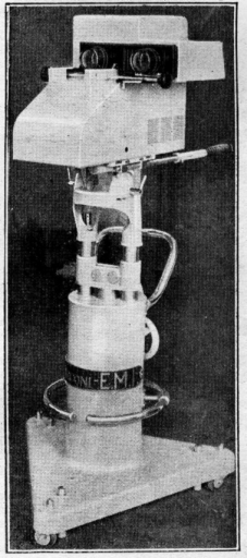
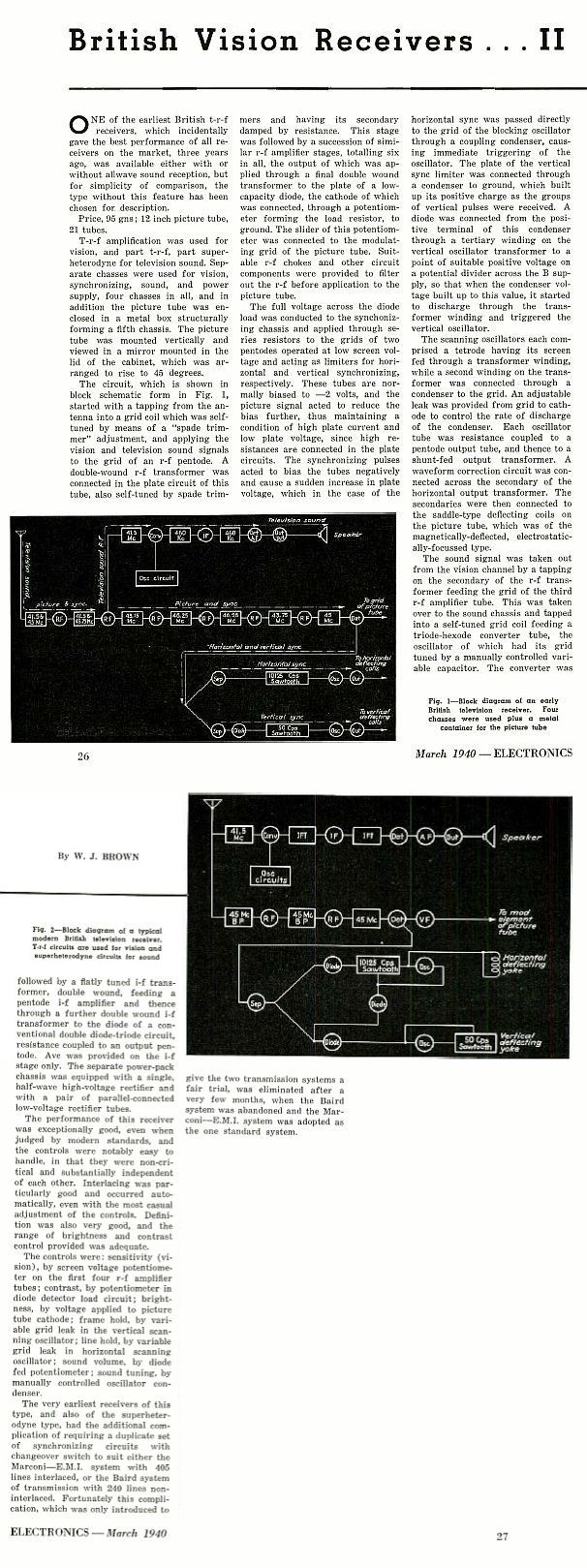
Pre-War Television Early Days In 1934 the Marconi-EMI Television Company Ltd was formed bringing together the transmitter technologies of the Marconi Company with the television studio equipment and receiver technologies of the EMI Company. The Marconi Company designed the aerial system and its feeder and the sound transmitter, but the vision transmitter and all of the studio equipment and receivers were designed by EMI. It was this combined company that provided the technology for Britain's television service in the years from 1936 through to the switch-off of the 405 line transmissions in the early 1980s. The very first dedicated television receivers developed by this alliance were the HMV model 901 and the Marconi model 702. These sets were essentially identical but had differences in the veneering of the cabinet and the shape of the speaker grill so as to appeal to traditional customer loyalties for the two brands. The same design of television circuitry was also incorporated into a number of other sets carrying the HMV and Marconi names that included radios and gramophones. Writing in the journal "Electronics" the author W. J. Brown was impressed by the performance of these first generation sets even if he did get the sound IF frequency wrong.. See the Complete Range of EMI First Generation Televisions. This web page takes a look at one of these early receivers. The HMV 901 Television
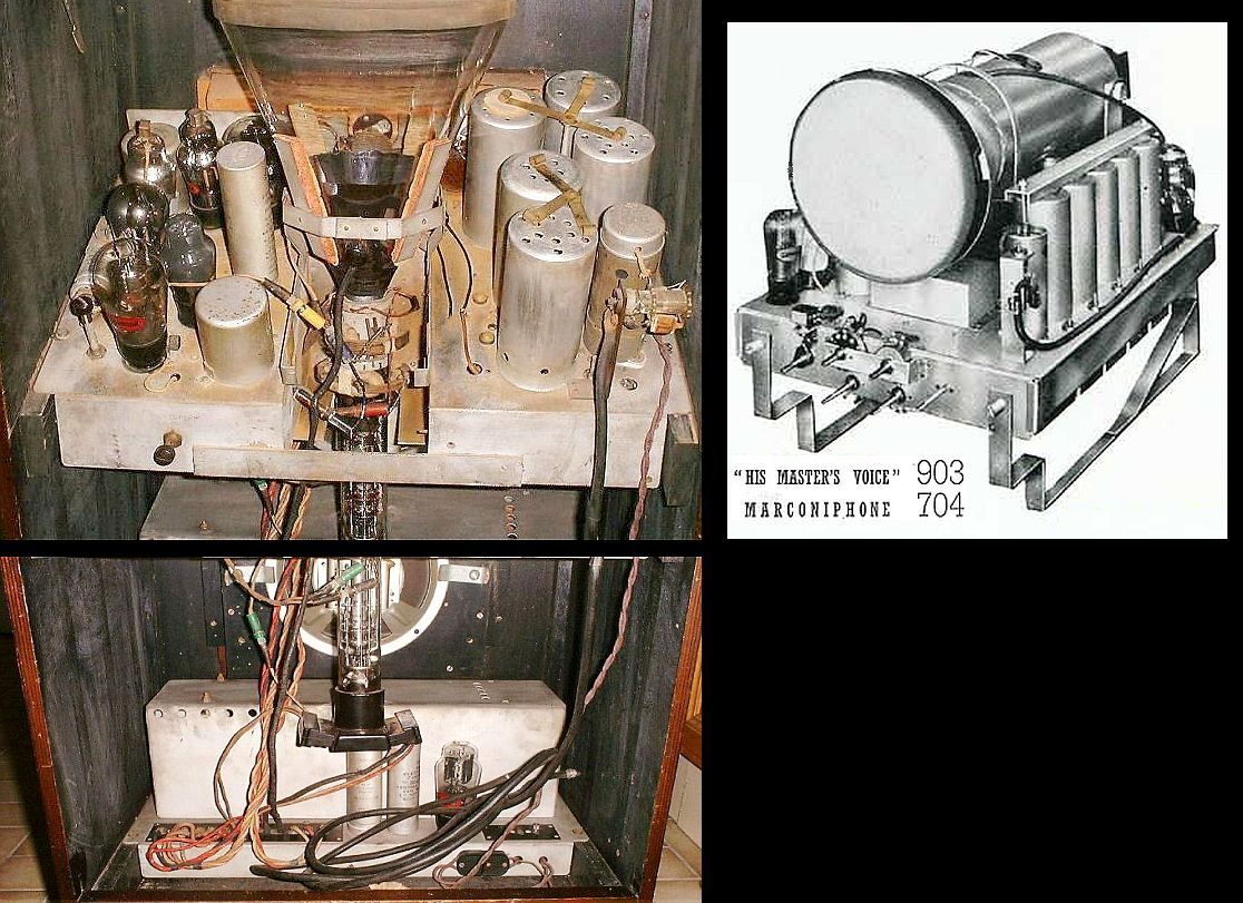
At this time there was only one television channel and one transmitter. This set is designed with a straight (TRF) vision receiver tuned to 45 MHz. and consists of six RF pentodes and a diode detector. These are contained in the screening cans on the left. There is no video amplifier. The detector connects directly to the CRT. So why a straight receiver rather than a super-het that would have been useful with the roll-out to regional transmitters on other frequencies? The reason was probably to achieve better signal to noise ratio. Frequency changers at this time had high internal noise relative to RF pentodes but a string of RF amplifiers operating at the same frequency brings the danger of unwanted feedback and oscillation, hence the spread out construction with cans screening each stage. To the right of the CRT are the synch separator and line and frame timebases and on the floor of the cabinet is the power supply chassis. The 5000 volt supply for the CRT final anode is generated from a step up transformer from the mains and this and the EHT rectifier are located below the timebase chassis in a metal box behind the two brightly lit HT rectifiers. Only a small part of the sound receiver is visible in this picture. It shares the first two RF stages with the vision receiver and its RF connection can be seen between the second and third cans from the top. Click on the picture for the valve layout.
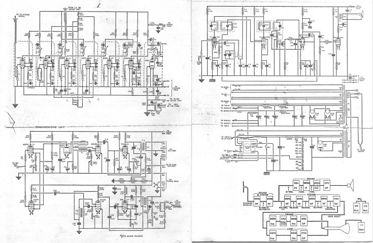
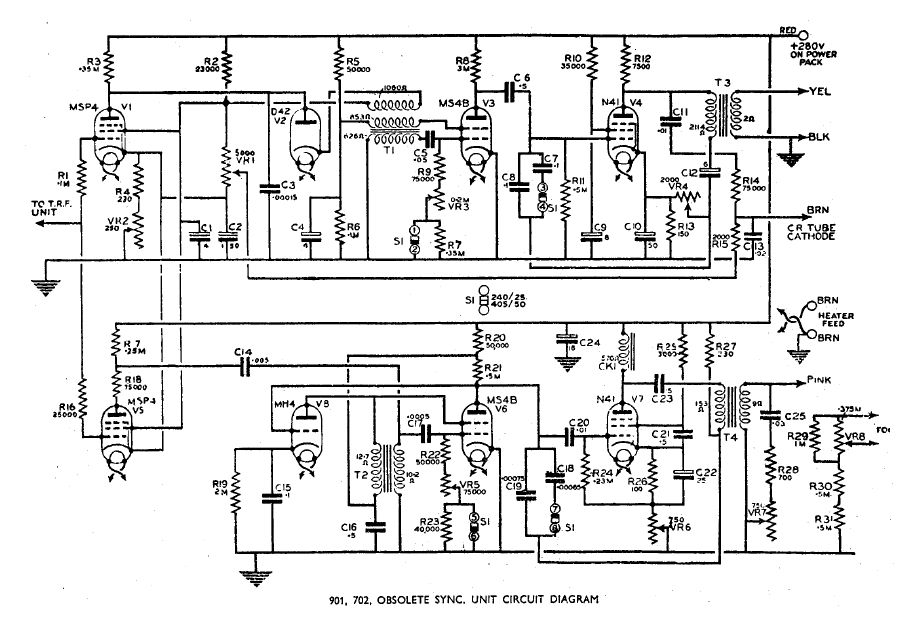
Click on the diagram below to see the schematics and layouts:
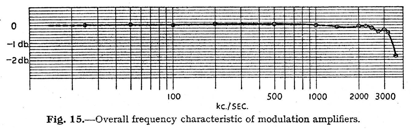
The test card image shows a slightly darkened central area and a concentrated dot in the greyscale blocks caused by ion burn. The user instruction booklet does say that before switching on the receiver the brightness control should be turned fully to the left and brought up gradually. Curiously they don't specifically suggest turning back to the left before switching off but they do warn about displaying a central spot or horizontal or vertical line. The CRT has no ion trap and no screen aluminising. If you click on the test card image you can see that this 80 year old set is still capable of reproducing 2.5MHz bars quite well and even gives a fair impression of 3MHz. This corresponds well with the characteristics of the Alexandra Palace transmitter of 1936 in which the overall response curve of the vision modulator was designed to be flat up to 2.5MHz and in practice was less than 0.3 dB down at 3MHz.
The EMI service notes say "A slight amount of frame crushing at the lower end of the picture is standard but in special cases only, a frame linearity control can be added provided that the Frame circuits have been thoroughly investigated." This set has no frame linearity control and shows the "standard" crushing. Another optional add-on was a picture centring coil or "push about coil" as EMI described it. This set had been fitted with one but it was found to distort the focus at the right side of the picture and adequate centring could be achieved simply by pushing the tube neck slightly to one side or another, thus shifting the screen within the rubber mask, so the coil was removed. Early sets have a less compliant screen mask that has 45 degree corners. The style of control knobs also changes between early and later sets.
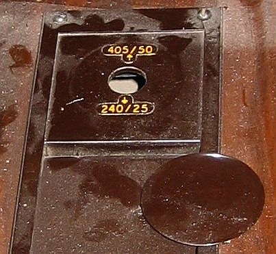
The Trial In January 1935 the Selsdon Committee, whose brief was to advise on the future of television, made its report. It proposed that the BBC set up a television station in London but it was unable to decide on whether the 240 line Baird system or the 405 line EMI system should be used and thus both systems should be trialled. The HMV 901 was one of the sets designed to meet the needs of this trial period. The early production units were fitted with a "System Selector Switch" and one additional valve in the timebase chassis. Blanking plates were fitted to the switch panel of sets manufactured after the decision was taken to proceed solely with the EMI system and most early sets also had their switches removed if they were subsequently refurbed by the factory. You can compare 405 line and 240 line test cards images here. Looking at a photograph of a 240 line Baird image it appears to compare quite favourably with the 405 line EMI images but what you are not seeing in the still photograph is the very noticeable flicker from the Baird 25 Hz frame rate. Apart from the political motives for trialling the Baird system it is really quite surprising that it was considered at all given the lack of a viable camera and the flickering picture. ...and what about 180 lines? The System Selector Switch has 4 poles and is marked S1 in the old timebase schematic. See Service Info
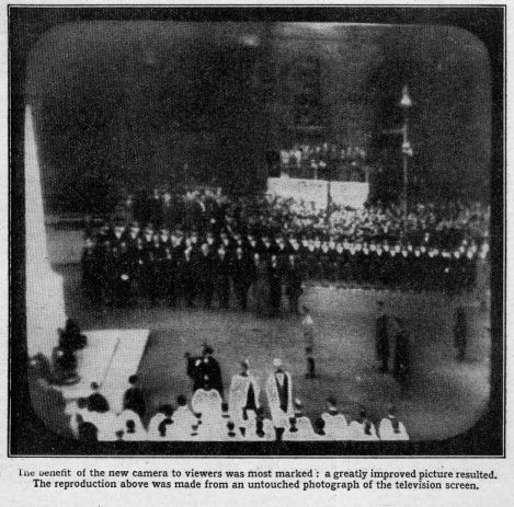
Whilst EMI took a very large gamble in deciding to develop a 405 line system using the Emitron camera that was based on the Zworykin Iconoscope there was really no contest when it came to the trial. The Emitron camera gave sufficient sensitivity to permit both studio and outside broadcasts due to its charge storage technique and cameras were portable although restricted by connecting cables. Against this Baird Television Limited (BTL) really had no practical camera. For studio work they were forced to employ either a spotlight scanner where the subject was scanned by a single point source of light in a darkened room whilst groups of photo cells picked up the reflection or the intermediate film camera, a cine film camera that was fixed to a massive high speed development bath combined with a mechanical scanning disc. The latter had to be bolted to the floor and mounted behind a glass window to suppress its noise. The only electronic and therefor portable camera that BTL had was the Farnsworth Image Dissector which, unlike the Iconoscope, had no charge storage and relied on an electron multiplier to achieve any form of sensitivity. The Farnsworth camera proved to be virtually unusable due to a combination of its distorted image and its lack of sensitivity and thus almost all BTL's transmissions were derived from mechanical scanning. The one advantage that the BTL system had over the EMI system was the lack of the image shading that required tilt and bend adjustments. This was especially true in the case of film transmissions where scene changes could be less predictable than those in the television studio. Demonstrations of both BTL and Marconi EMI systems were given at Radiolympia in August 1936 but the official start of the trial period commenced on the 2nd of November 1936 with a short opening ceremony on the BTL system and repeated on the Marconi EMI system. Thereafter regular program transmissions were given week about on the two systems. The BTL opening ceremony was televised using the intermediate film camera but the Farnsworth camera was also used as a back-up in case of problems as can be seen in the photo. Thanks to Dicky Howett's research of the BBC "Television Program as Broadcast" record we have a true account of the opening ceremonies from 405 Alive as archived in the BVWS. At a meeting of the Television Advisory Committee, TAC, on the 16th of December 1936 the BBC Director of Television, Gerald Cock submitted a very damning report of the experiences of operating the BTL system and that along with adverse comments from the television manufacturer Cossor sealed its fate. Baird Television Limited were given the opportunity to make representations to the TAC on the 23rd December but it was clear from their response that they accepted the outcome. The last Baird system transmission took place on the 11th February 1937. The Emitron Camera Click on the camera for more information
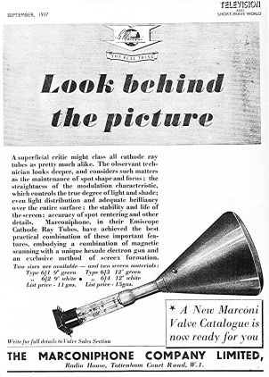
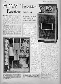
For a fuller account of the start of High Definition Television in Britain see: BFI ScreenOnline The Wireless World Click below to see what The Wireless World said about the H.M.V. Television Receiver Model 901 in January 1937
The Wireless World tested a very early model of the HMV901. In
the
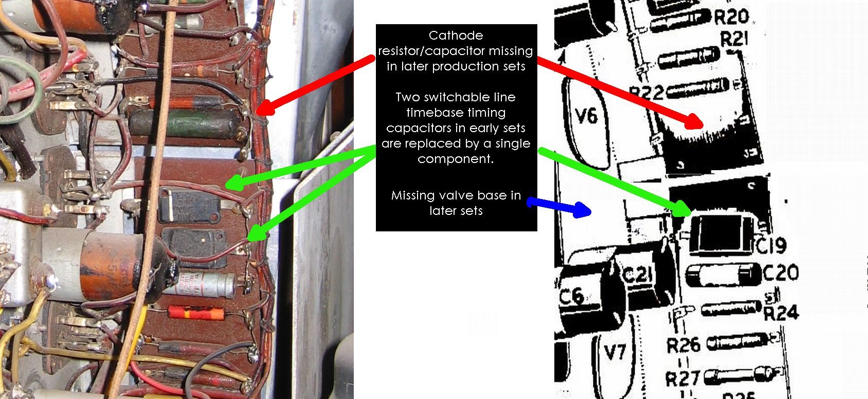
photos below you can see the following differences with later models: .jpg) Whilst there don't appear to be any survivors of the early WW style HMV901 the earliest surviving sets do have the longer CRT metalwork and components of the additional triode valve V8 used to maintain regular behaviour through Baird System frame synch pulses. EMI had a patent (425220) on the inclusion of line synch information within the frame pulses that might explain why the Baird frame syncs didn't. The early EMI timebase including the four ganged switches for selection of 240 or 405 standards and the V8 triode can be seen here. The set pictured below has the longer CRT metalwork and a vacant valve holder on the left of the timebase chassis whereas other sets have blanking plates. I believe that sets without the Baird circuitry have their plates mounted on the underside of the chassis whereas sets that do have the circuitry fall into two camps, those with and without a plate. In this case the plate is mounted on the top side of the chassis. These plates could have been fitted at a subsequent refurb but this would have required the valve holder rivets to be drilled out so perhaps these plated sets were just the last production run prior to Baird deletion.
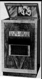
A Prototype HMV901 / Marconi 702 ?
A few years ago a set came to light that externally looked rather similar to the HMV901 that Wireless World tested in January 1937. I had thought that this might have been a prototype for the HMV901 and its cousin the Marconi 702. The set differed from the WW set in that it had its controls mounted on the front of the cabinet and a 9" CRT instead of the 12" but it had a very similar veneering pattern and design of speaker aperture. The chassis was totally different to the HMV901 / Marconi 702 and mounted at a slight angle to the horizontal and divided into a timebase on one side of the CRT and an RF amplifier on the other. The power supply was mounted in the floor of the cabinet and the EHT parts were shielded in similar style to the 901/702. The set had no back panel and no obvious way that one was ever fitted. Nor did it carry any HMV or Marconi decal or serial plate. More recently in discussion with David Boynes he suggested that rather than being a prototype for the 901 and 702 that it was more likely a prototype for the HMV903 and Marconi 704 that were introduced in early 1937. This does make good sense because as David pointed out the prototype chassis has its aerial connection attached to a coil mounted on a metal bracket and coupled to the top cap of the first stage in a very similar way to that on the 903/704 chassis which uses a superhet configuration with the first stage using an X41. It looks as if EMI had decided at quite an early stage to move away from the straight TRF vision receiver circuitry of the first sets with a view to the roll-out of television to other parts on the UK that would demand alternative sound and vision frequencies. The 903 and 704 were offered at a price less than half the initial price of the 901/702 and their construction may have given a small reduction in manufacturing cost but the profit margin must have been severely reduced. Further to the above, in a description from the current owner the set apparently has a 405/240 standards switch which suggests that its development was at least coincident with the 901/702 if not earlier.
The Hasler Landi In 1939 the Hasler company constructed their own version of the HMV901 for demonstrating television at the Swiss National Exhibition (known as the Landi). The Hasler Landi still exists in the Museum of Kommunikation in Bern Establishing Manufacturing Dates Most sets have a small white plastic serial plate mounted on the rear. The coding of these is not entirely obvious but the 4 digit numbers stamped onto the chassis assemblies probably indicate the time sequence of manufacture. Some data can be seen here.
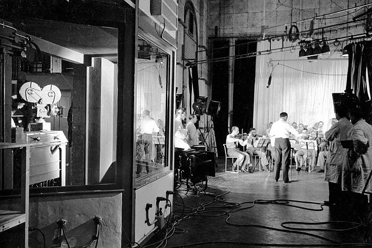
Studio Monitors Given that Marconi-EMI were supplying all the studio and transmitter equipment then it's no surprise that the BBC also used their domestic receivers as studio monitors. The photo on the left below is from the Radiolympia. The viewing window on the right of the control room gallery sketch overlooked the EMI studio and can also be seen in the centre of the Alexandra Palace cut-away drawing and in the BBC trade test film. The centre photo below is also from the EMI studio control room gallery. Thanks to Andy Emmerson writing in 405 Alive we can get an impression of the activities of the Control Gallery.
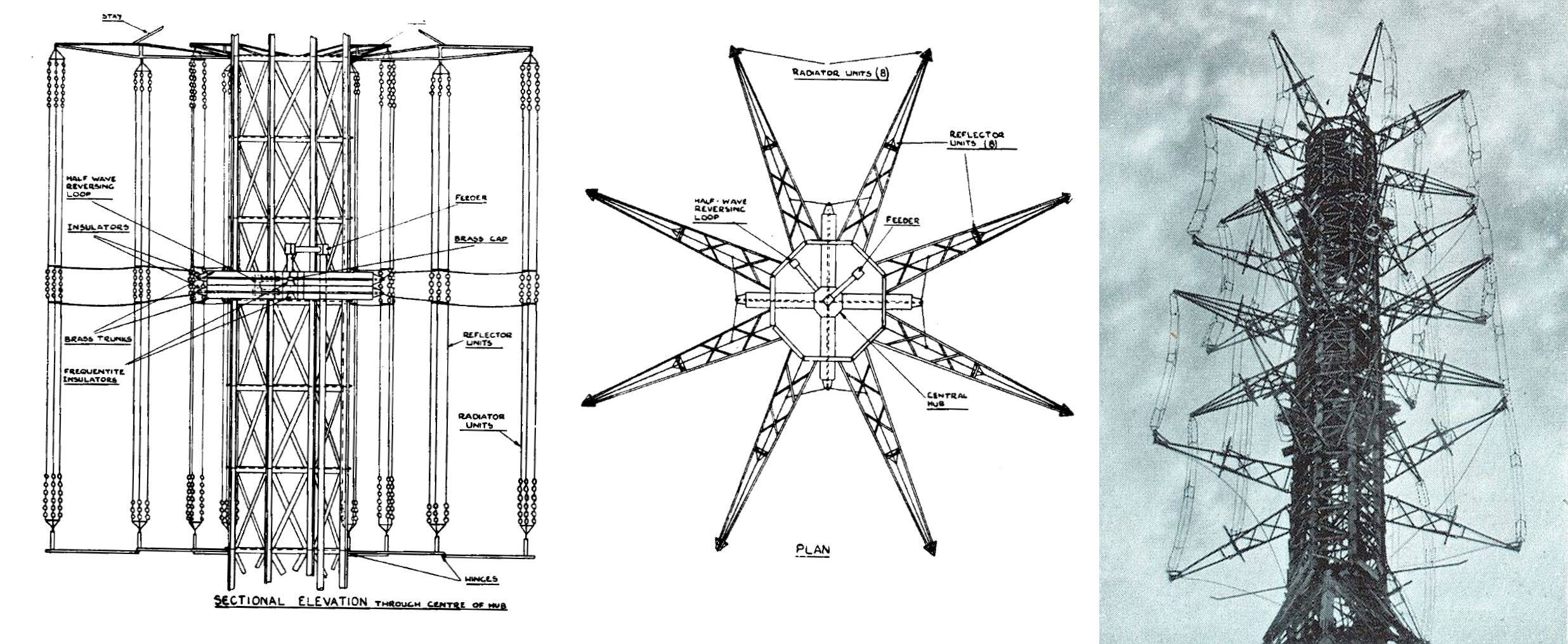
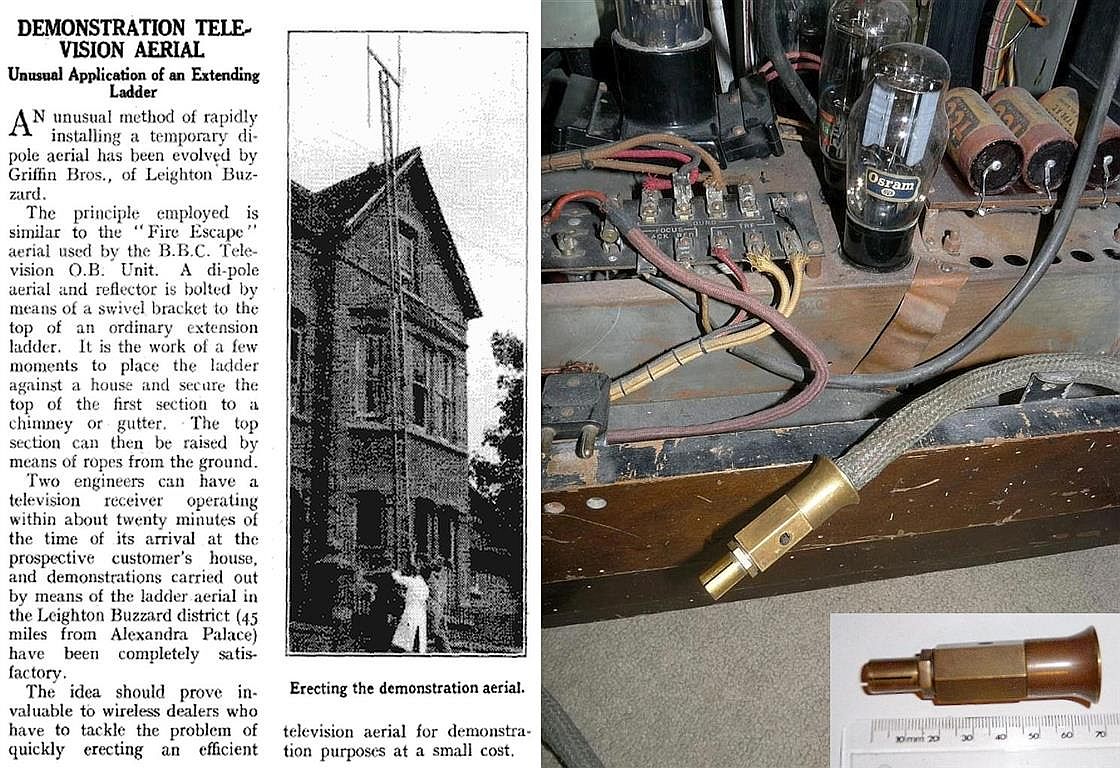
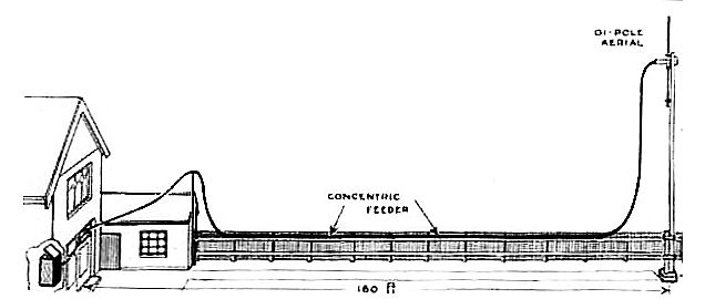
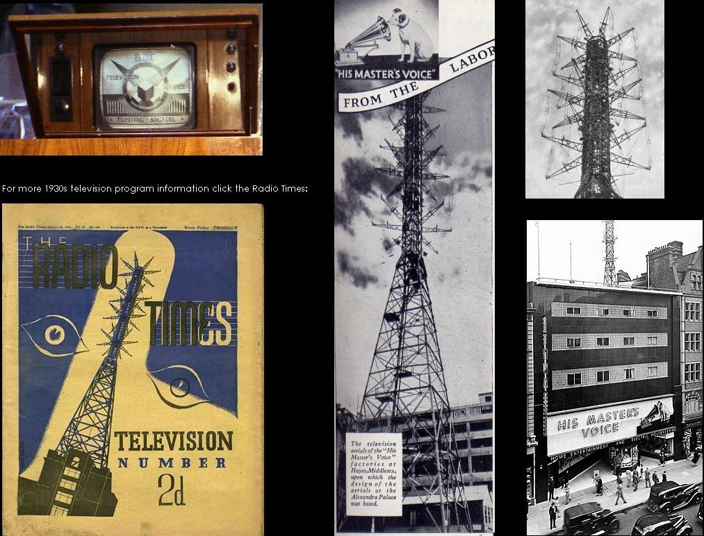
Aerial Construction
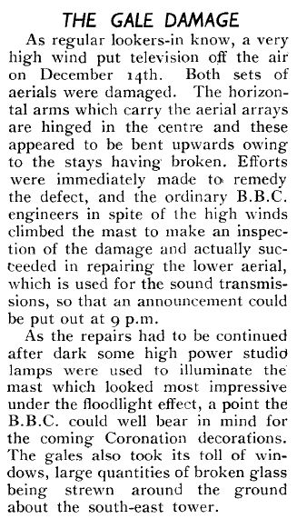  The aerial mast was a copy of the mast and aerial system built at the EMI Hayes works. A full technical description of the Marconi-EMI television system as installed at Alexandra Palace can be found here.
When I
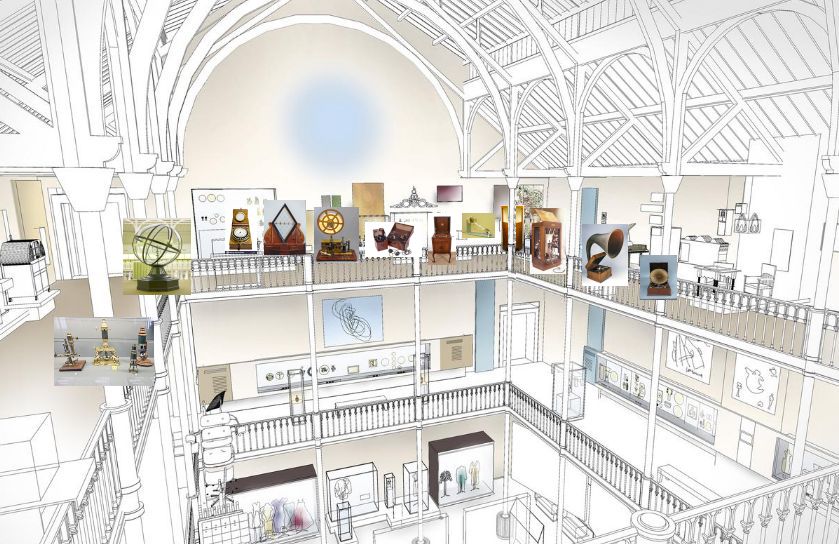
was a kid I used to love visiting The Royal
Scottish Museum in Edinburgh. It was a fascinating place crammed with
wonderful technological exhibits. A great variety of early microscopes and other
scientific instruments filled several cases, a
very large working orrery
lived in a glass sphere. Early telegraph and telephone equipment occupied one wall, crystal sets
and early valve receivers, early and prototype
Emitron camera tubes, phonographs and gramophones of all types another. In
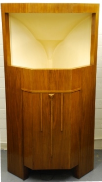
one corner stood an impressive
Voigt corner horn and in another case (but now in
store) a beautiful EMG with giant papier
mache horn but the exhibit that fascinated me the
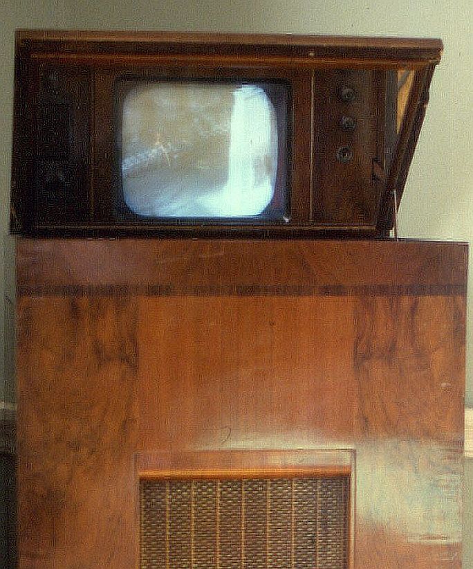
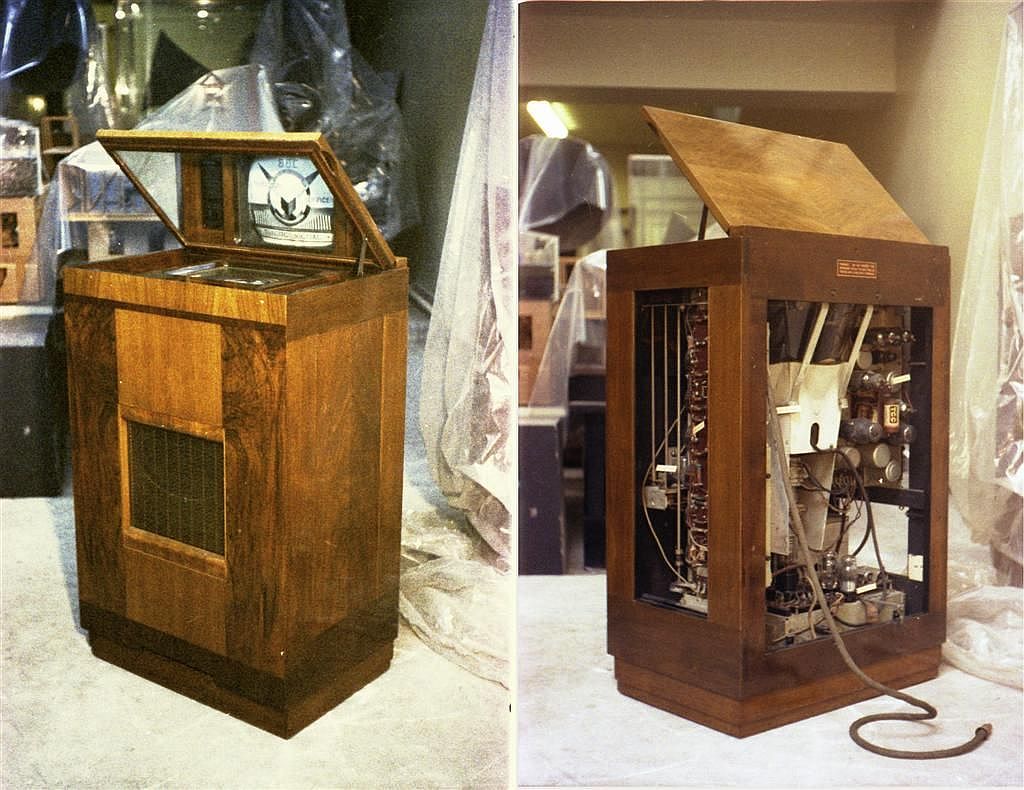
most was the 1936 HMV television. The model 901 was displayed in an island display
case with glass on all sides so that you
could see all the works with little labels identifying the major assemblies and it used really vintage technology, valve
types that dated from the early 30s. For me,
growing up in the 1950s, television was a modern thing but here was a
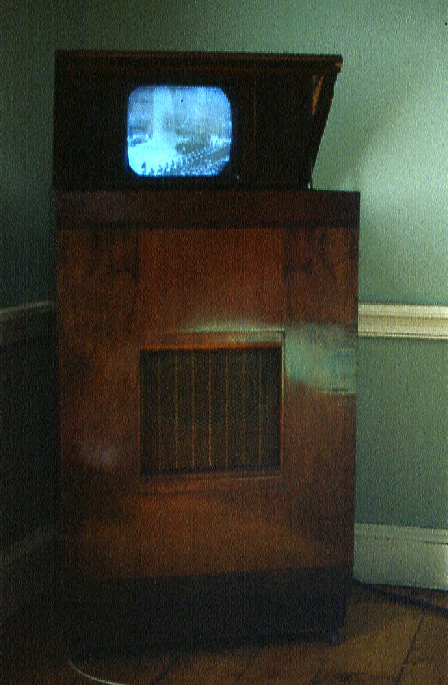
television from the past. The tube had a very small deflection
angle and was therefor rather long and had to be mounted vertically in the cabinet
and viewed through a mirror in the lid.
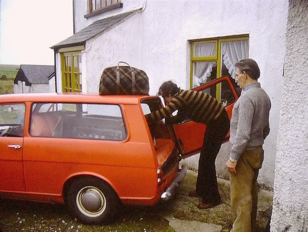
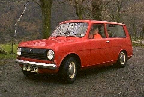
Moving on further in time I subscribed to the "Antique Wireless Newsheet" by Tudor Rees for old radio enthusiasts and decided to place an advert for a pre-war television. At the start of the war about 19,000 sets had been sold in Britain but I was aware that the survival rate was very low. Whilst some early televisions had formed parts of radios and radiograms I really wanted one that had no other purpose than as a television and ideally it should be manufactured by EMI given that it was their research and technology that had led to the birth of real television in Britain. My ideal was either a Marconi 702 or an HMV 901. I received two replies to my advert, one from someone else looking for a pre-war set and asking if I could pass on any replies that I wasn't interested in, and much to my delight, a reply offering an HMV 901. The only slight drawback was that I was in Edinburgh and the set was in Cornwall. As I recall the seller, Michael Scott (no relation) wanted £120 for it. This was in 1978 and that was quite a lot of money but we set off in our Reliant Rebel Estate (which had cost less* than the HMV) and needless to say I bought it. Being a fragile box of tricks it lay on a double air mattress in the back of our car and did survive the journey. * Admittedly the low price of the Rebel was because it had a con rod through the side of its block when I bought it and it was located at a remote hill farm in the Lake District. It was quite a nice little car although I had owned more interesting vehicles previously. Below: Following purchase in October 1978 the HMV901 is loaded into the back of my Reliant Rebel for the 500 mile trip back from Cornwall to Edinburgh.
Having not been used for many years it took me quite a bit of time to
get it working. The worst problem was the mains derived EHT transformer
that was burnt out but fortunately my employer had a transformer shop
at the time and after a couple of goes at rebuilding it I got a design
that gave sufficient insulation to work and survive. You
can see some of the service data
and the transformer design here
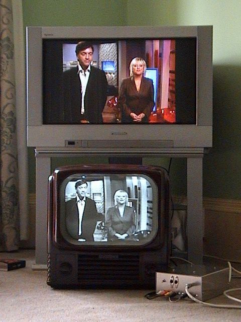
. You can see more on the faults in my HMV901 here. The 405 line broadcasts were closed down in early 1985. In the years leading up to 1985 the broadcast authorities produced programs using the current 625 line standard and with the aid of a 6 foot high rack of equipment were able to generate 405 line versions of the same programs to maintain the old service. Technology has moved on considerably since 1984 and a number of innovative designs have been produced for standards converters in recent years. Instead of 6 feet of equipment, the converter can now be contained in a small metal box.
The converter in the picture above is based on the designs of Darius Mottaghian and is shown converting today's broadcast material into the 405 line signal that is being received by an early 1950s Bush TV32.
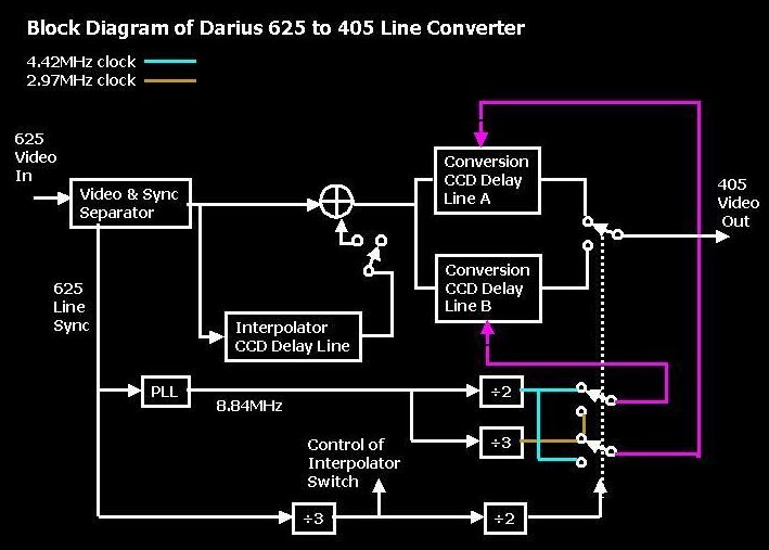
The converter uses 3 charge coupled device delay lines. Two of these form the 625 to 405 conversion and the third provides interpolation for the one line in every 3 that is discarded. Analogue samples from a 625 line are clocked into one of the CCD delay lines whilst the other is having its stored line content clocked out at a rate suitable for the longer duration lines at 405. When this is complete the roles of the two CCDs are reversed etc etc. You can get more detailed information about Darius' standards converter here
An Alternative to Standard Conversion Recently it has become possible to generate both 405 line and 240 line signals displaying any form of video or still images by use of a PC with a graphics card. The comparison between the two systems is interesting. The increased line rate of the 405 system is noticeable but the presence of flicker in the 240 line system is the most noticeable difference. Some information on this technique is given here.
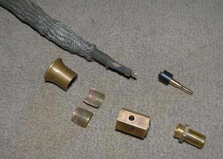
The Aerial Plug You may notice in the museum photo that the aerial cable and plug are substantial to say the least. Whilst my set came complete with the original cable it was missing the plug. Being a sucker for ancient technology I had been looking out for a replacement but in more than 30 years of looking I was unable to track one down. I mentioned this on a vintage radio forum and very kind and skilful fellow forum member Brian Cuff offered to make a replica and also the mating socket. Many thanks also to John Wakely the owner of the original plug who had some years earlier created drawings and more recently made his plug available for copying. Below are photos of the original EMI plug with ruler and the artificially aged replica fitted to my aerial cable. The co-ax itself has two layers of braiding and gutta percha insulation for the inner conductor.
A short video of the fashion parade from the 1937 Television Demonstration Film The short video above shows the HMV901 displaying a clip from the BBC 1937 Television Demonstration Film. The source was a 625 line VHS tape captured on a PC using Honestech TVR then streamed to the graphics card and modulated for 405 line operation with the original 45MHz/41.5MHz carriers in a Darius modulator and fed into the aerial socket of the HMV901. Occasionally you will see narrow dark horizontal bands on the the picture. These are only aliasing effects from the camcorder that is capturing the scene and are not present in reality.Below are some longer clips from the 1937 Television Demonstration Film. The video camera has rather poor noise performance in low light levels. The film does give some impression of the types of items broadcast but it has rather poor sound quality and strange overhead lighting. Unfortunately the ambient light level allowed my camera and tripod to be reflected in the screen. A truer impression of picture quality is given in the 1946 trade test film further down this web page.
Norman Green's Excellent Lecture Although titled as the Televising of the 1948 Olympic Games at least half of the lecture is devoted to the pre-war era of BBC Television and gives very interesting coverage of the control rooms and outside broadcast equipment not to mention actual filmed coverage from a television screen. This process was done by Cinema Television and was very much in its infancy. Only 202.5 lines of each 405 line frame are filmed and spot wobble was used to hide the loss of half the lines.
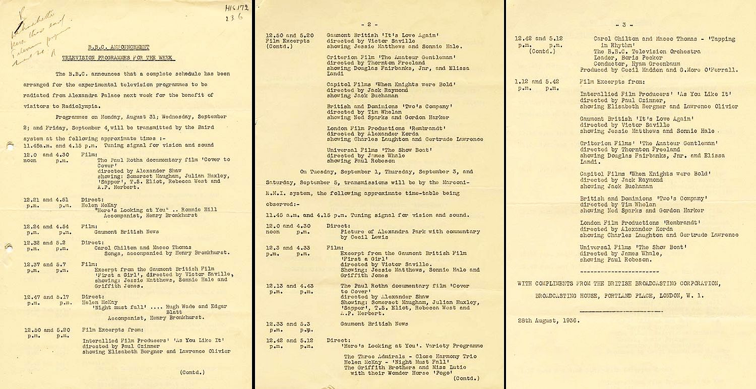
In October 1936 the Wireless World reported the impressions of an observer in Welwyn (Captain Ernest H. Robinson) who had been watching the early program material from Radiolympia and Alexandra Palace."The features which drew the greatest appreciation were the outdoor shots at the Alexandra Palace grounds (which never failed to excite the astonishment and wonder of those who had come with no idea of what modern television can do), the variety entertainment in the studio, with its striking use of successive shots from various angles, and, among the films, the news reels and the excert from "Show Boat." On the other hand, in studio programmes, head-and-shoulder views and interviews soon bored the watchers. Frequent change of scene and viewpoint seems to be probably even more important in television than in the cinema. This is where the variety show scored, and although the "Show Boat" excert was simply of Paul Robeson singing "Ol' Man River" the film producer has presented this song with rugged simplicity of masses, and of light and shade, that it makes perfect television entertainment. Films with intricate small detail (particularly noticeable in captions) and films which were static, were the least effective. The lighting of studio scenes seemed to vary considerably, but of course in this, and in the matter of make-up, the television producers will have to feel their way for some time. When the camera moved rapidly towards or away from an artist there was a frequent tendency to go out of focus, evidently because the cameraman has at present no sufficiently positive rapid-focusing device. The most remarkable effect of television in my house was its enthusiastic adoption by children. They have never shown any great interest in sound broadcasting - even the Children's Hour. But television they watched with rapt attention, and with screams of laughter for the comic horse in the variety show; and not merely once. They insisted on seeing the programme through again and again as it was repeated daily for Radiolympia. They never tired of it, which seems to indicate that it was not the "novelty appeal" of television which was having effect, but real entertainment value." Gerald Cock, Director of Television gave his vision of the future in The Radio Times in October 1936. "Here's Looking at You" and "Picture Page" Following on from the productions in "Here's Looking at You" televised by Cecil Madden for Radiolympia there followed a number of test transmissions in the period leading up to the official opening ceremony on the 2nd November 1936 and Madden conceived "Picture Page" where various short performances were introduced by Joan Miller acting as a type of telephonist connecting the viewers to the action. This format proved to be popular and was produced by George More O' Ferrall for many further episodes. A fter the official opening ceremony on 2nd November 1936 the following programs were listed...
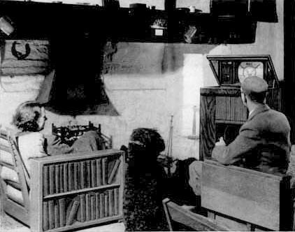
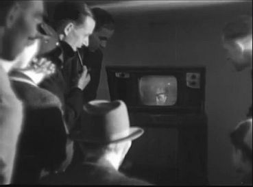
....and when there was nothing else, you could always sit and watch the tuning signal. Critic Alan Hunter (below with his wife and dog) was very pleased with his HMV 901 and in March 1938 wrote as follows: "My television parties are becoming quite a social success, over and over again, as “The End" fades up on the screen and the lights are switched on, I hear this remark: “It is much better than we imagined it would be,” And it is, you know. Ever so much better. I have just been looking at "The Crooked Billet" television's longest thriller. It really was thrilling. So was "Black Magic" not long ago (25th Feb. 3.25). But it is the unending kaleidoscope from Alexandra Palace of people and things I should never have time or inclination to see any other way that “make television.” When, therefore, I am asked by "H.M.V." whether I would miss television if it were taken away, I really must protest that the question is almost monstrously ludicrous. Only over my dead body (metaphorically speaking, I hope!) will they take my television receiver away from me - ever."—
Visitors to the Radiolympia show in August 1936 could see television demonstrated on a number of different manufacturers' sets
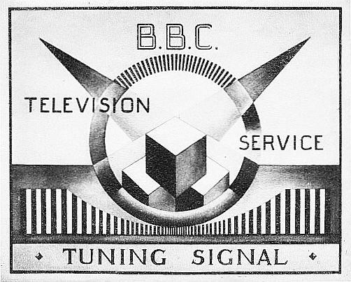
In June 1937 the public had another opportunity to see television sets from various manufacturers operating at the Science Museum Television Exhibition. The early BBC Tuning Signal shown in the domestic scene above is rather interesting. The Royal Scottish Museum set had a paper copy of this placed on top of its CRT screen. Other early Tuning Signals can be seen here.
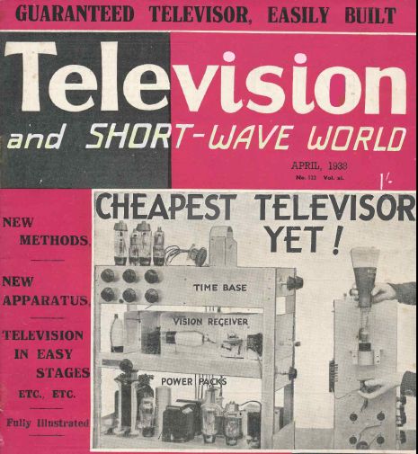
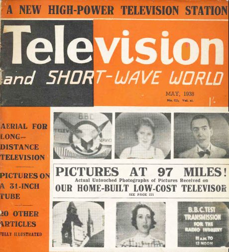
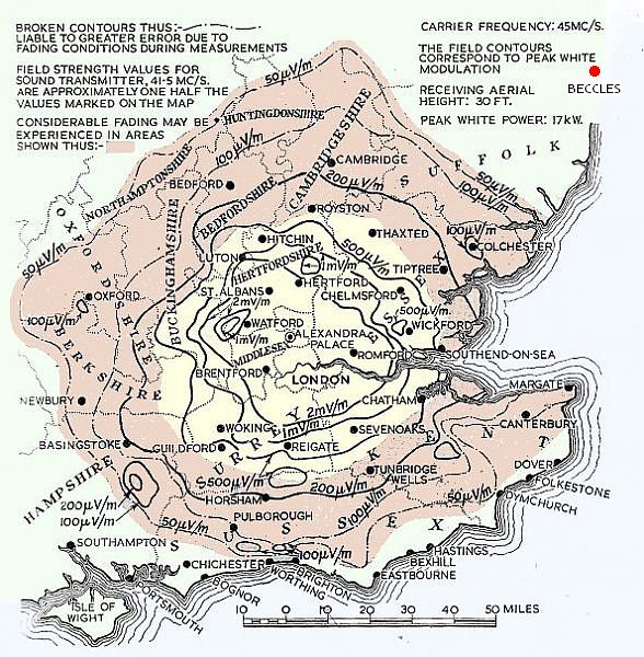
By 1938 receivers were still quite expensive items and a number of home build designs were available. Television & Short-Wave World announced their simple design in March 1938. In the May 1938 edition the designer, Spencer West published results photographed off the screen as received (near Beccles, Suffolk. See map below.) 97 miles from the Alexandra Palace transmitter. Then in June 1939 a Mr W.F. Steel reported using an earlier, more complex receiver design also by Spencer West and published in the same magazine over several issues starting in October 1936 but with an added RF stage to receive pictures in Minehead, a distance of 170 miles from the transmitter. Yet another Spencer West design appears in August 1937.
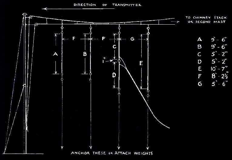
The aerial used by Spencer West in Beccles was a rather interesting Yagi with two directors and a reflector hung as if from a washing line.
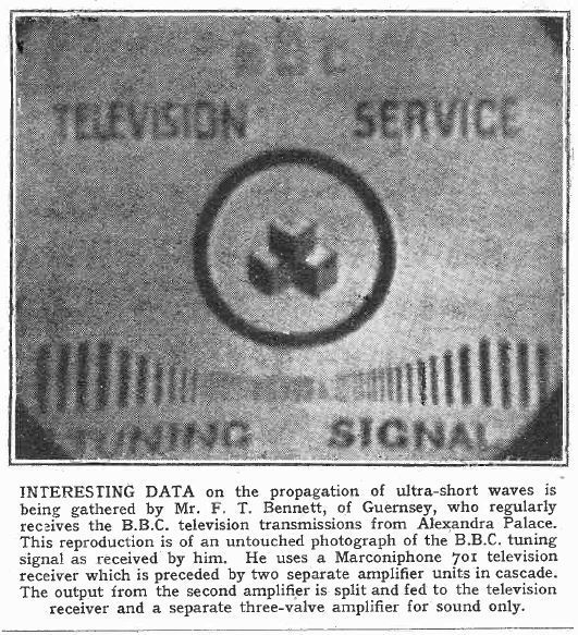
Guernsey is 200 miles from Alexandra Palace. Sales of Television Receivers By the end of 1936 sales of television sets totalled 427. In January 1937 the BBC received 74 replies to their viewer questionnaire. Asked which make of set they had the answers were: 29 Marconi-EMI 21 Baird 14 Cossor 4 GEC 6 Other By the end of 1937 the total sales of television sets amounted to 2121. An excellent record of the programs transmitted on BBC Television from 1936 to 1939 can be seen here. By the end of 1938 the total had risen to 9315. At the start of the war in September 1939 the total sold was 18,999.
Did the BBC provide the world's first regular high definition television service? That depends on how you define HD. The End of Pre-War Television Broadcasting Shortly before the BBC Television Service closed in 1939 a short film was made on the terrace in front of Alexandra Palace showing anti-aircraft defences. This gives views of several Emitron cameras in action.
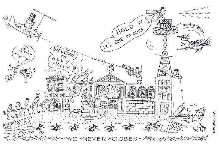
O n the 1st of September 1939 the BBC Television Station at Alexandra Palace closed down for the duration of the war. In the previous 3 years viewers had been presented with 380 plays, 138 variety shows, 165 special studio features, 8 plays from London West End Theatres, 262 editions of "Picture Page" and 56 outside broadcasts. (Source: The excellent Teletronic website.)During the war the Alexandra Palace television sound transmitter played a major roll in countering the Nazi bombers in The Battle of the Beams with cartoons by Paff. Paff also gives us some more insight of events at Alexandra Palace in war time in 405 Alive as published in the BVWS.
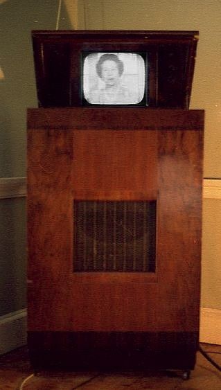
After the war and taking account of the 1943 Hankey Report of the Television Committee and no doubt influenced by the fact that 19,000 television sets had been purchased by 1939 the BBC in 1946 restarted television broadcasting using the same 405 line standard and this choice was confirmed by their own internal research report of 1948 and was extended to other regions of the UK and continued until the early 1980s. The following film clip was used for trade test transmissions in the hours not covered by normal program transmissions. Introduced by Jasmine Bligh you can see the EMI control room and control gallery in operation and Elisabeth Weich sings "Stormy Weather" followed by Jack Billings tap dancing, accompanied by Debroy Somers and his Band. The video was taken from the screen of the HMV901 whose rear view is shown at the start of this web page. The vision and sound signals are being received at 45 and 41.5MHz respectively from a PC graphics card feeding the Darius modulator. Please ignore the aliasing bars caused by the camcorder that periodically run up through the film. These are not present on the HMV901 screen. The cathode ray tube has no ion trap or aluminising of the screen hence the slightly brown colouring in the centre of the picture. Unfortunately the ambient light level allowed my camera and tripod to be reflected in the screen.
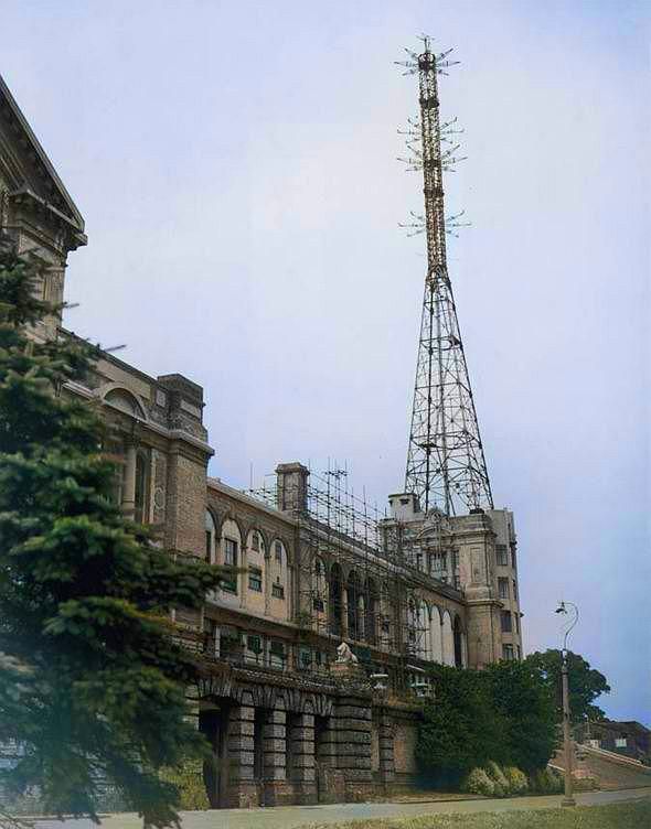
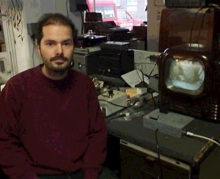
Oldest Working Television Jeffrey Borinsky holds the title for the oldest working television in Britain. Jeffrey's set carries the Marconiphone badge and has a slightly different cabinet. design but is otherwise the same as the HMV901. 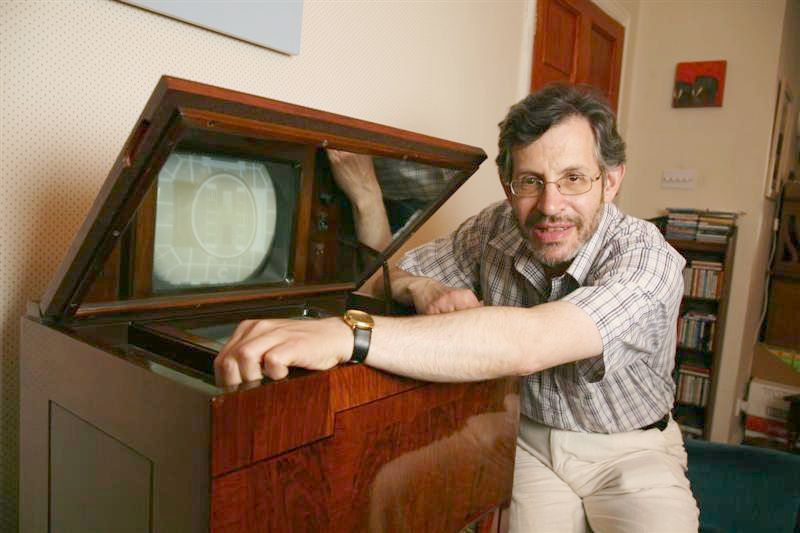
|
|
.jpg)

.jpg)
.JPG)
.JPG)
.jpg)
.jpg)
.jpg)
.jpg)
.jpg)