|
A Comparison
between the SS Engine and the XK
I was reading William
Heynes' paper to the Institute of Mechanical Engineers on "The Jaguar
Engine" published 1953 and found one or two interesting comparisons
that put us in our place.
Firstly the XK head design apparently results in much simpler
machining and a very significant weight saving. The alloy XK head
weighs about 50 lbs but would have been 120 lb in cast iron.
Comparing the hemispherical combustion chambers of the XK with our
lozenge shaped chambers, or heart shaped for the side valve engines,
the XK gives a fairly obvious benefit in that the valves are not
socketed by the chamber and Heynes shows the increase in air flow rate
of the inlet valve for four types of engine. A side valve unit, a Mark
V, an XK120 and an XK120C. All four engines being of similar capacity.
Our cars have 5/16" valve lift and I've added a red line at this value
on the graph.
See also:
Jaguar and the Gas Meter
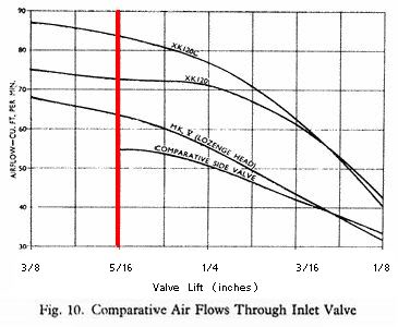
The results are:
Side Valve...55 cu ft/min
Mark V........64 cu ft/min
XK120.........72 cu ft/min
XK120C.......84 cu ft/min
Apart from the big flow rate advantage Heynes describes how the OHC
arrangement of the XK removes the side loads on the valve stems that
are an unfortunate feature of using rockers as in our OHV engines and
causes stem wear and can lead to valve sticking.
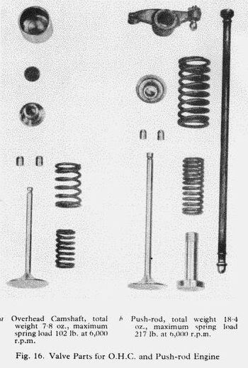
The simplicity of the XK valve train gives a halving of the mass of
components when compared to our OHV engines. The SS components add up
to 18.4 ounces whereas this is reduced to a mere 7.8 ounces in the XK.
This significant reduction in mass permitted much lighter pressures to
be applied by the valve springs and whilst quoted at 6000rpm the
maximum spring load was reduced from 217 lbs down to 102 lbs in the XK.
Heynes points out that this reduced spring pressure gives significant
benefit in terms of valve seat wear and lessens the possiblity of
valve breakage.
Another design element that Haynes covers is the XK crankshaft. He
points out how the centre main bearing carries much larger stresses
than the intermediates and to address this they arranged the oil
passages so that the centre main is supplied from the oil gallery as
usual but it in turn is not required to pass on the oil to adjacent
big ends. This is not the case in our engines and it was certainly
true that the centre main in the last one I dismantled showed fatigue
failures not apparent in the intermediates.
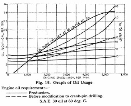
Haynes also shows an interesting graph of the flow rate provided by
the XK oil pump plotted against engine revs. but more interesting are
the plots of flow rate through the engine for crankshafts of the
original design and then for a design with modified oil passage
drilling. The original oil feed to the big ends exits at the point of
greatest radius of the crank and it throws the oil out of the big end
bearing due to centrifugal force. The effect of the centrifugal force
is reduced at smaller radii so the modified big end oil feed exits
through another drilling at right angles to the original drilling and
is thus positioned half a crank pin thickness less.
As you can see from the graph, even at moderate r.p.m. the modified
drilling significantly reduces the quantity of engine oil required to
maintain a given oil pressure.
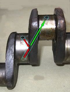
Unfortunately our crankshafts have their big end feeds at the point of
maximum radius. The picture below shows our shaft with oil being fed
(in red) in from a main bearing and how it is supplied (in green) to
the adjacent big end bearing at the point of maximum radius of the
crank.
Finally, a 4 cylinder comparison of the
SS 1½ litre engine with the
experimental XG engine that used a similar head design to the
BMW328. Apparently the valve gear proved to be rather noisy until they
fitted additional return springs on the exhaust pushrods. The XG
actually used the same block as the 1½
litre but the original head studs were not conveniently positioned for
the new head. For this experiment they had to reposition some studs to
places where they were simply screwed into the thin top deck without
the usual reinforcement.
N.B. The two sections are not taken at
the same location on the block, hence the apparent lack of an oil pump
in the XG.
.jpg)
| 